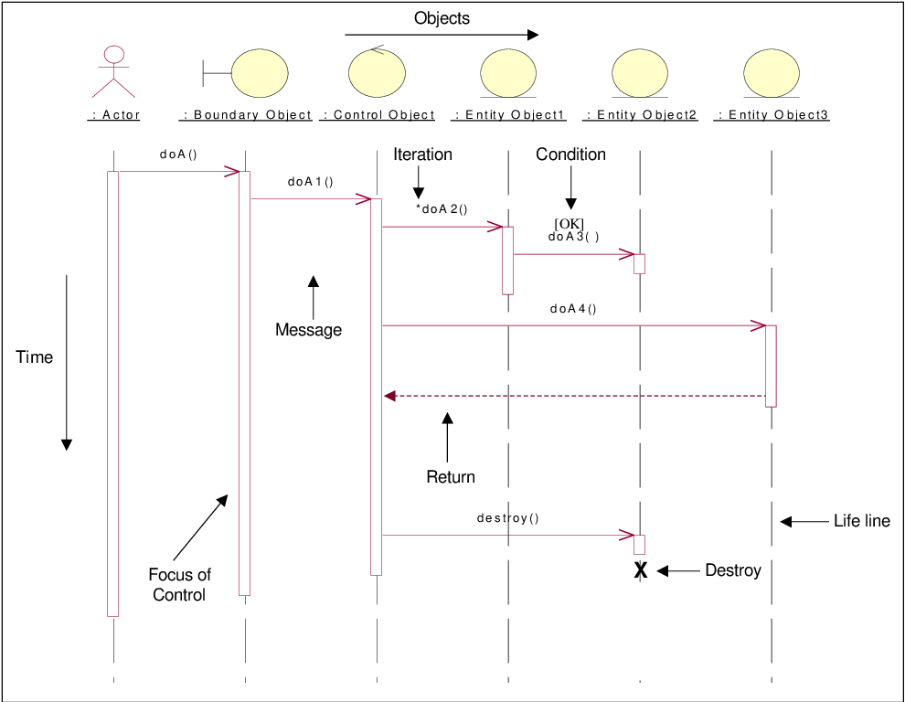
In the latter case, the lifeline is terminated by a stop symbol, represented as a cross. They are denoted going to or coming from an endpoint element.Ī lifeline may be created or destroyed during the timescale represented by a sequence diagram. Found messages are those that arrive from an unknown sender, or from a sender not shown on the current diagram.

Lost messages are those that are either sent but do not arrive at the intended recipient, or which go to a recipient not shown on the current diagram. It is shown as creating a nested focus of control in the lifeline’s execution occurrence. The first is the source object sending two messages and receiving two replies the second is the target object receiving a synchronous message and returning a reply and the third is the target object receiving an asynchronous message and returning a reply.Ī self message can represent a recursive call of an operation, or one method calling another method belonging to the same object. In the previous diagram, there are three execution occurrences. In the following diagram, the first message is a synchronous message (denoted by the solid arrowhead) complete with an implicit return message the second message is asynchronous (denoted by line arrowhead), and the third is the asynchronous return message (denoted by the dashed line).Ī thin rectangle running down the lifeline denotes the execution occurrence, or activation of a focus of control. Messages can be complete, lost or found synchronous or asynchronous call or signal. Boundary, control and entity elements from robustness diagrams can also own lifelines. This will usually be the case if the sequence diagram is owned by a use case. Sometimes a sequence diagram will have a lifeline with an actor element symbol at its head. If its name is "self", that indicates that the lifeline represents the classifier which owns the sequence diagram. A lifeline will usually have a rectangle containing its object name. Sequence diagrams are not intended for showing complex procedural logic.Ī lifeline represents an individual participant in a sequence diagram. Sequence diagrams are good at showing which objects communicate with which other objects and what messages trigger those communications. Just as with component diagrams, these groupings are represented as file folders.UML 2 Tutorial - Sequence Diagram Sequence DiagramsĪ sequence diagram is a form of interaction diagram which shows objects as lifelines running down the page, with their interactions over time represented as messages drawn as arrows from the source lifeline to the target lifeline. Packages: A UML shape that allows you to put different elements into groups. For example, Psycho Killer is outside the scope of occupations in the chainsaw example found below. All use cases outside the box would be considered outside the scope of that system. System boundary boxes: A box that sets a system scope to use cases. In complex diagrams, it is important to know which actors are associated with which use cases. Use cases: Horizontally shaped ovals that represent the different uses that a user might have.Īctors: Stick figures that represent the people actually employing the use cases.Īssociations: A line between actors and use cases.

Here are all the shapes you will be able to find in Lucidchart:
Uml sequence diagram symbols how to#
You can use this guide to learn how to draw a use case diagram if you need a refresher. The notation for a use case diagram is pretty straightforward and doesn't involve as many types of symbols as other UML diagrams.


 0 kommentar(er)
